SSU-24ExEi power supply and signal transmission module
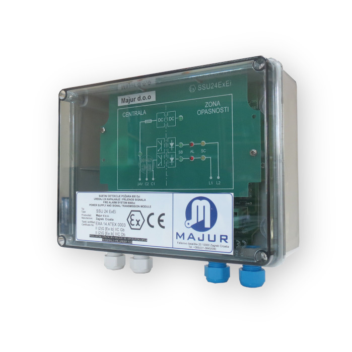
SSU-24ExEi device for powering and transmitting signal from the sensor-sensor.
The task of the SSU-24ExEi is to:
- galvanic separation of self-safe (detectors-sensors) from non-self-safe circuits (Fire Alarm Central fire alarm panel )
- limitation of voltage and current in circuits inside the spaces threatened by the explosive atmosphere of gases, vapors and dusts (Ex space)
- functional compatibility with fire alarm equipment outside Ex space
Explosion protection of the enclosed space with the 800Exi system has been realized
then and only then if an SSU-24ExEi device was used between detectors in
Ex space and other equipment, and if all equipment is 800Exi properly
designed, installed, used and maintained.
The SSU-24ExEi consists of several essential parts:
- galvanically separated power supply, DC / DC converter with current and voltage limitation
- switchgear signal transmitter assembly to fire alarm system with galvanic separation by optoisolators and switchgear and voltage limiting circuitry to switchboard side optoisolators (Fire Alarm Central)
- switchgear and voltage limiter assembly for switchboard SSU-24ExEi (Fire Alarm Central)
- signaling of DC / DC converter correct operation of two green LEs for detecting power supply of SSU-24ExEi device and detector
- signaling of the state of the detector for each channel separately (L1, L2)
- - LED green = steady state (SB)
- - LED red = alarm state (AL)
- - LED yellow = fault short circuit (SC)
|
Number of lines (channels) (L1 and L2) |
2 chanel |
|
Number of detectors per channel |
10 detectors maximum |
|
Parallel connection |
FORBIDDEN |
|
Supply voltage |
Unap = 20 - 28, 8V |
|
Maximum output voltage on line L1 and L2 |
Uomax = 25,2 V |
|
Maximum short circuit current L1 and L2 |
Iomax = 38,1 mA |
|
Maximum capacity of line L1 or L2 |
(IIC) Co = 107 nF, (IIIC) Co = 820 nF |
|
Maximum permissible inductance of line L1 or L2 |
(IIC) Lo= 24 mH, (IIIC) Lo = 97 mH |
|
Maximum output power per L1 or L2 |
Po = 0,24 W |
|
Maximum allowable Lo and Ro ratio by L1 or L2 |
(IIC) Lo/Ro = 148 μH/Ω |
|
Device body dimensions (L x W x H) |
197 x 150 x 75 mm |
|
Color |
Gray RAL9018 |
|
Fuses: F1 (Littelfuse typ201 or 217; ESKA No.521.000) F111, 211 (0.08 A MT / 250 V ESKA No.887.006.) |
0,125 A M / 250 V
|
|
Maximum voltage of the device power supply error |
Um = 253 V |
|
Weight |
650 g. |
|
Ambient temperature |
Tamb = -20⁰ C do +55⁰ C |
|
Standby power consumption at L1 and L2 |
80 mA |
|
Water and dust protection |
IP24 |
|
Type of protection for gases and vapors: Industry (above ground), Zone 1 and 2, intrinsic safety, group of gases IIC (hydrogen, acetylene), installation outside the enclosed space |
Ex II (2)G [Ex ib Gb] IIC |
|
Dust protection type: Industry (aboveground), Zone 21 and 22, intrinsic safety, conductive dust IIIC (ρ ≤ 10 kΩm) installation outside the enclosed space |
Ex II (2)D [Ex ib Db] IIIC
|